Tests to evaluate our turbine over the long run go on.
Despite the weather we are measuring the performance of our prototypes.
New wind turbine design.
Despite the weather we are measuring the performance of our prototypes.
Industrialization has brought many advantages like safer and healthier life style, increased mobility opportunity, better communication, better farming, increased productivity etc. To sustain our improved lifestyle we need energy, a lot of energy. The demand for energy has doubled in the last 40 years and with the global population rapidly growing and developing nations eagerly accessing industrialization the demand for energy will increase with unprecedented rate: it is estimated that by 2040, the world’s energy consumption will have increased by almost 50% . We are currently using more than a million terajoules of energy every day . More than half of our energy comes from fossil fuels (oil, natural gas and coal). This comes with some heavy tolls. Increased pollution and greenhouse gases level, environment degradation, and rapid consumption of non-renewable sources are the major issues we need to face. The adopted strategies to address these challenges are on one side to improve the efficiency in the consumption and in the grid management, on the other side to implement a shift in where we get our energy from by improving the use of renewable sources. In recent years the use of renewable sources such as wind, solar, hydro and geothermal, has steadily increased thanks to new technological advancements and an increased awareness and demand for “clean” energy. Currently, around a fifth of the world’s primary energy supply comes from renewable sources, but to overcome the big energy challenge and the future increased demands more needs to be done. The other side of the coin is that also the production of energy through renewable sources has some impacts on the environment: the visual impact, the use of land, and the impact on wildlife just to mention a few. Between 1990 and 2016 wind power increased from 3,8 TWh to 599,4 TWh with an average annual growth of 21,4%. In 2016 23,2% of total electricity production came from wind power . In 2015 wind power constituted 15.6% of all installed power generation capacity in the European Union and it generated around 11.4% of its power . However, electricity generated from wind can be discontinuous depending on the season and on the velocity and direction of the winds, thus requiring to be replaced by other sources during low winds periods. This represents one of the major cons related to wind power. One notable aspect about wind (and solar) energy is that it can be produced by small turbines, as such they can be conveniently installed in small factories or private houses. This represent an interesting trend as it allows delocalizing the production and diminishing the overall need for energy transmission. On the other side, turbines currently available on the market require medium but (almost) constant winds and, in order to better catch the wind, they are usually tall and bulky. These two aspects represent heavy limitations for installation in urban environment and therefore for the wider adoption of wind generated energy.
Since the beginning of this century wind energy has seen a constant and steady increase as an alternative to fossil fuels. The availability of small-scale turbines has made possible the use of wind energy for residential usage generating a new market segment that goes under the name of Small Wind Power Market (below 100 KW). The increased demand for residential usage has determined the emergence of companies specialized in the design and production of turbines residential use. Vertical axis turbines appear, however, to be the preferred choice for this specific market segment. The reduced dimensions and the catchier design of Vertical axis turbine favour the installation in urban environment (less visual impact, aesthetically appealing). The Small Wind Power Market segment has witnessed a growth rate of about 30%, it represents therefore, one of the most promising markets for the upcoming decades. This segment is expected to continue growing also thanks to governmental aids that are pushing private citizens to become more autonomous and less dependent from the grid. This trend signifies also excellent business opportunities.
The majority of small wind turbines are horizontal axis or vertical axis wind turbines, usually with blades of 1.5 to 3.5 meters they can produce up to 10 kW at the optimal wind speed. The requirements for a small wind electric system to work are: 1) presence of enough wind; 2) the local regulations allow the building of tall towers; 3)  enough space. While horizontal axis turbines need to be oriented to face the incoming wind, vertical axis wind turbines are not sensitive to the direction of the wind. TAO is the result of several years of studies, mathematical models and prototypes that allowed the development of the current prototype. The resulting TAO is a totally new concept of turbine in which the rotation of the blades occurs along an axis that can orbit around the central pole thus decoupling the blades movement from the rotor rotation. The movement is steered by the upper blade (see figure on the right) that allows TAO self-orienting in the direction of the wind. The two blades rotate along their axis, without interfering, meaning without the return losses that are common in vertical turbines. This design choice allows to obtain a smooth functioning and to decrease the turbine’s dimensions and at the same time to increase the generated power resulting in an increased efficiency, i.e. maximizing the energy extraction also with low speed winds. Moreover this design makes the turbine less sensitive to the wind direction and velocity. For its characteristics, TAO is the ideal solution for areas with low/slow winds, where the productivity of commercial turbines is less efficient. TAO comprises three main components: 1) the blades that catch the wind’s energy, 2) the generator that transform the wind energy into electricity, and 3) the synchronizing group that manages the movement of the blades with the wind. The synchronizing group comprises a special gear (figure below), which allows a smooth transfer of the movement from the wind to the generator and represents the real innovation.
The orbiting axis constitutes a true paradigm shift in wind turbine. First of all it allows the synchronizing group to smoothly orientate the blades towards the wind so that there is always one blade (the one facing the wind) working and producing electricity.
In terms of efficiency TAO has the same efficiency of vertical axis turbine but with reduced dimensions (one third of a commercial turbine).
TAO Energy Srl has been established specifically for the marketization of TAO, building on pre-existing relationships among the members that were involved in the studies and development of TAO prototype. The collaboration for the prototype started back in 2009 when Ubaldo Bernardi had the intuition that an orbiting axis would improve the turbine efficiency. Together they built several prototypes in Piro Impianti’s plant

experiencing several challenges (e.g. energy loss – due to the friction generated during
the rotation, which caused a rapid wear of the gears). Their efforts paid off and the current prototype was finalized and installed at PIRO Zootechnical plants premises where it is still operating.
The company was formed by the following members:
We start from an analysis of the stationary machine: It assumed null the angular velocity of the blade around the main axis ω = 0.
The lift and drag values are dependent by incidence of the blade section relative to the wind direction, for simplicity in the analysis of the breakdown we will write only P and R to indicate the functions P (i) and R (i) with i = angle of incidence.
We define: b the distance of the blade section from the main axis, α the angle that describes the position of the blade and V the speed of the true wind.

We calculate the length of the arm in function of α:
b = 2 r abs ((sin (α / 2))).
We calculate the resistance of the blade along the tangent of the circle that represents the direction in which the blade is free to move: R ‘= R cos (α), the other orthogonal component is nulled by the constraint .
We calculate the moment (M) respect to the main axis:
M = b*f = b*R’ = – 2 r R cos(α) ∣sen(α/2)∣
From this formula we obtain:
We can observe that in the starting phase, when angular velocity is null, the wind resistance contributes negatively to the displacement of the blade for a half cycle (-90 °> α <90 °) in which the arm is, however, smaller and the resistance the same is lower due to the transverse position to the wind of the blade.
Contrary with 90 °> α <225 ° there is a positive contribution of the resistive component on the half cycle which has longer arm.
Assuming a linear relationship between the coefficient of resistance and angle of incidence with a maximum value of R = 1, setting b (max) = 1 and S = 1 we have the trend as in the figure:

We try to do a similar analysis to the lift force generated by the blade:

We define
β = α – 90 °
as the angle between the lift vector and the direction of the blade ( tangent line on the α position).
we can write the P component of the lift as P ‘= P cos (β).
then:
We can therefore say that: the contribution of the lift to the motion of the blade is always positive except for α = 0 ° and α = 180 °, respectively, in which they cancel the arm length and lift force.
Here, respectively, the graphs relating to the lift contribution (| cos (β) | * | sin (α / 2) |) depending on the angle α and, approximately, the value of the coefficient of lift force (Cp (i)) based on the angle of incidence (α / 2) for a flat surface:


By product of the two graphs you get the trend of the force transmitted to the machine from the lift force.
The peak of lift occurs with an angle of incidence of about 15 ° (flat surface) which corresponds to α = 30 ° where the contribution of the lift blade movement is about 70 ~ 80%.

In the above image we try to establish how the apparent wind vector (v ‘) is positioned respect to the (section of) blade when the tangential velocity is close ( or equal) to the true wind speed (v).
We can see as, approaching the tangential velocity to the real wind velocity, the vector v’ tends to form a smaller angle respect to the profile of the blade (i => 0 °), and in consequence of this:
The resistance tends to decrease considerably and its vector tends to rotate counterclockwise.
 The lift force occupies a major role in generating force to be transferred to the machine and improves the efficiency with the approach to an angle of incidence of 15 ° (maximum lift of the yield, see image on the left) that is obtained with a tangential velocity equal to ~% 96 true wind speed.
The machine behaves as resistive generators (eg Savonius) with vertical axis with resistance operation at startup, this also leads to a lower start-up wind (speed lower cut).
As the speed increases, the behavior is like to wind turbines with horizontal axis, where the lift force becomes the main component in the generation of the force that actively contributes to the motion of the blade.
In next post an detailed analysis on blade profile…stay tuned.
p.s. : Sorry for my bad english.
In the image below you can see how the blades are synchronized.
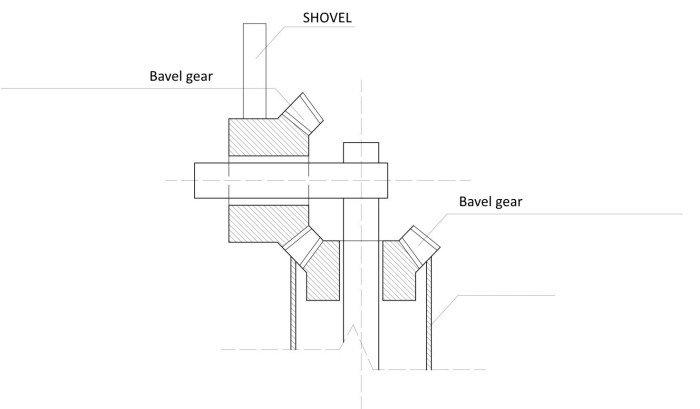
The synchronization is done simply with two bevel gears (ratio 1: 1): one fixed on the static part of the machine (called jacket) and the other is fixed to the movable arm of the shovel which therefore rotates with the same angular velocity of the vertical axis.
The prototypes in the following video are based on this construction method: